In the U.S., recent waves of tech innovation and adoption have greatly altered the nation’s economic landscape. These waves have brought both the diffusion of new technologies into new regions (with local economic benefits), but also intense clustering of jobs and businesses related to them, which has contributed to vast inequality among regional economies.
This is the subject of the current report. A companion to the earlier Brookings paper that warned about the uneven geography of AI activity, the discussion here reviews the AI location problem and highlights key federal, state, and local policy moves that could counter it.
The report begins by reviewing the intensely concentrated nature of the overall AI industry (as opposed to the recent boom in generative AI) and suggesting the need to widen the sector to ensure broader participation. (At a few points the report touches on the specific growth trajectory of generative AI applications.)
After that, the report recommends an array of federal, state, and local actions that could promote more even geographic development as the industry enters a new growth stage powered by generative AI.
Ultimately, the report suggests that policymakers now have an opportunity to bring about more geographically inclusive development for one of the most important innovations of our time. . .
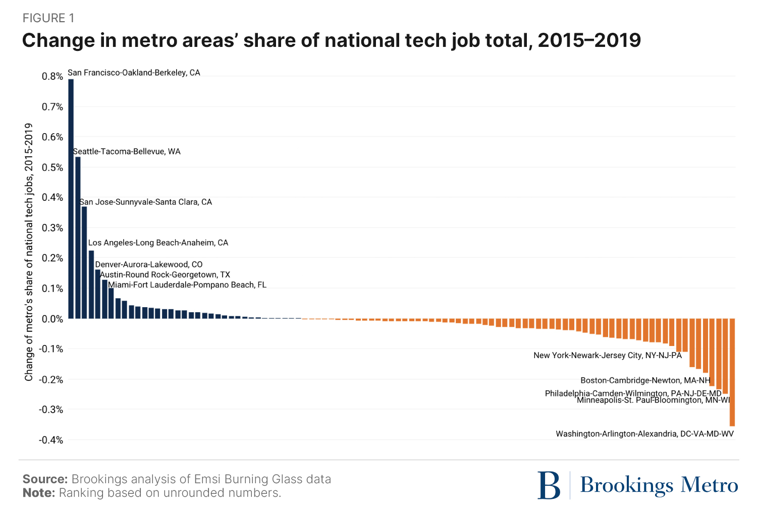
And Brookings Metro recently described a similar “winner-take-most” dynamic in six digital service industries, where the concentration of employment in a short list of “superstar” metro areas has been increasing over the last decade.
Despite the known benefits of such industry clustering, the uneven geography of tech is not always benign.
As an innovation matter, the nation’s hyper-concentrated tech geography may be narrowing the range of possible tech advancements and creating harmful imbalances among firms, local ecosystems, and the resources they command.
And as an economic development issue, such imbalances tend to create large pools of high-skill workers in some areas while other areas suffer a “brain drain” that leaves lower-skill workers behind.
also say only 6 metro areas (San Francisco, San Jose, New York, Los Angeles, Boston, and Seattle) accounted for nearly half (47%) of the nation’s generative AI job postings from January 2023 to May 2023, according to new
As
climate change gets worse, we’re only going to see more and more
radical ideas for how to prevent the planet from heating up to
unbearable temperatures. Geoengineering—the process of using
technologies and new innovations to artificially cool the planet—comes
in many forms, but one of the most prominent methods that scientists are
pondering is to literally obscure the amount of sunlight that hits the
planet. The idea is that if we reduce the amount of solar radiation that
hits the planet, we may be able to help the planet cool down quite a
bit and avoid the most destructive outcomes in store for us with runaway
climate change.
Apart from sounding like the literal plot to an episode of The Simpsons, solar radiation management (SRM) seems wildly impractical in most current proposals.
Most plans involve either injecting clouds or dust into the atmosphere
to increase reflection of sunlight back into space; or reducing the
amount of incoming radiation from the sun via solar shades made of a
light reflective material like graphene. That would effectively mean
building a giant shield in Earth’s orbit and having it sit out there
like a floating beach umbrella, blocking out enough sunlight so the
planet can cool down just a tad...
There are many obstacles with deploying and maintaining a solar shield in space, but one of the biggest is simply mass.
Solar radiation can induce a small amount of pressure on an object, so
over time, a solar shield will be pushed away slowly and may eventually
be blown out of its orbit entirely. It needs to be heavy enough that it
can withstand such pressure, but this also means building something that
is entirely too difficult to launch into space or too massive to build
easily in orbit itself.
As the planet bakes, scientists are putting forward increasingly
outlandish ideas to curb climate change. The latest: a gigantic shield
between the sun and the Earth that blocks out the heat.
Just because the idea is far-out doesn’t mean it wouldn’t work. That’s the takeaway of a study published Monday in the journal Proceedings of the National Academy of Sciences, writes Chelsea Harvey.
The
idea is simple in theory. A massive, reflective sunshade built between
Earth and the sun could help cool the planet by blocking out some
incoming solar radiation. In fact, engineer James Early first proposed a version of the plan in 1989, and it’s been bouncing around the fringes of climate geoengineering conversations ever since.
The
new study by theoretical cosmologist István Szapudi is reviving the
idea by proposing a potential solution to one of the sunshade’s major
problems: its weight.
It’s so heavy To avoid being
dislodged from space, scientists concluded the sunshade would need to
weigh at least a few million metric tons — for reference, the Hoover Dam
comes in at 6.6 million metric tons. Something that huge could be
expensive, time-consuming and a nightmare to transport.
But
Szapudi, who is based at the University of Hawaii, found that it’s
theoretically possible to build a smaller shield and tether it to a
heavy counterweight, such as an asteroid, to hold it in place.
1 day ago · A giant, reflective sunshade, constructed in space between the Earth and the sun, could block a small amount of incoming solar radiation and ...
A parasol for the planet - POLITICO
www.politico.com › 2023/08/01 › a-para...
22 hours ago · A massive, reflective sunshade built between Earth and the sun could help cool the planet by blocking out some incoming solar radiation. In fact ...
Solar radiation management with a tethered sun shield
István Szapudi
19 - 24 minutes
Edited by Neta Bahcall, Princeton University, Princeton, NJ; received May 3, 2023; accepted June 7, 2023
July 31, 2023
120 (32) e2307434120
Abstract
This
paper presents an approach to Solar Radiation Management (SRM) using a
tethered solar shield at the modified gravitational L1 Lagrange point.
Unlike previous proposals, which were constrained by the McInnes bound
on shield surface density, our proposed configuration with a
counterweight toward the Sun circumvents this limitation and potentially
reduces the total mass by orders of magnitude. Furthermore, only 1% of
the total weight must come from Earth, with ballast from lunar dust or
asteroids serving as the remainder. This approach could lead to a
significant cost reduction and potentially be more effective than
previous space-based SRM strategies.
Sign up for PNAS alerts.
Get alerts for new articles, or get an alert when an article is cited.
Climate change is a looming threat to the way of life for a significant fraction of humanity (1). As “greenhouse gases” such as CO2 and methane increase in the atmosphere, it retains a larger fraction of solar energy (2, 3). Solar radiation management (SRM) is a geoengineering approach (4, 5)
that aims to reduce the amount of solar radiation absorbed by the Earth
to mitigate the effects of climate change. Two strategies proposed for
SRM involve adding dust or chemicals to the Earth’s atmosphere to
increase the reflected fraction of sunlight (6–8) or reduce the incoming radiation from space with solar shades (9–12) or dust (13).
Despite the potential of SRM to mitigate the effects of climate change, it has faced criticism e.g., ref. 14.
Nevertheless, given the severity of the problem, any avenue that might
lead to the partial mitigation of a catastrophe should be investigated.
Since modifying the Earth’s atmosphere appears riskier, we focus on
space-based SRM strategies next.
One of the biggest hurdles for
proposals aimed at blocking a small fraction of sunlight from space is
weight. In space, weight translates into unrealistic costs. The
preferred location for a sunshade is beyond the L1 Lagrange point toward
the Sun, where the solar radiation pressure and gravity of the Earth
and the Sun are in balance. Advances in light materials, such as
graphene, could produce extremely light solar shades, similar to solar
sails (15).
These could be lifted into space at a relatively modest cost.
Unfortunately, any such structure is subject to the McInnes bound (16):
the balance of the gravitational forces and solar radiation pressure
sets a minimum weight or, equivalently, a minimum surface density for a
shade to be in equilibrium beyond the L1 point. The minimum surface
density required is orders of magnitude above that of graphene, making a
significant cost reduction infeasible with this emerging technology.
The
gravitating mass of a shield must be inside the L1 point, while the
efficiency of a shield increases toward the Earth. Dropping the
constraint that the two are in the same location, this paper proposes a
configuration to overcome the McInnes bound: a tethered sun shield with a
counterweight toward the Sun. The total weight of our proposed shield
can be significantly lower than the McInnes bound. Moreover, only the
shield structure weighing 1% of the total must come from Earth. Lunar
dust or material from asteroids can serve as ballast. Therefore, the
needed work (potential difference times mass) and thus the cost can be
many orders of magnitude below the McInnes limit. As such, our solution
offers a promising avenue to address the challenges of climate change.
In
the next section, we sketch out our proposed configuration and provide
an approximate calculation demonstrating how it circumvents the McInnes
bound. The final section summarizes the results and discusses some of
the caveats.
Sun Shields
Tetherless Shields.
The L1 Lagrange point is about 1.5 × 10⁶
km from Earth, which is 1% of the Earth–Sun distance. It is a preferred
location to park satellites since the Sun and Earth’s gravity are
balanced. It is also a natural place for a sun shield (9). Note that the L1 point is weakly unstable along the Sun–Earth axis and stable in the perpendicular plane.
For a solar screen, the solar radiation pressure will modify the point where all the forces are in balance (9).
The lighter the screen, the closer the balance point shifts from L1
toward the Sun. The following equation determines the equilibrium
orbital radius r:
[1]
where M⊙ and M⊕ are the mass of the Sun and the Earth, respectively, r⊕ is the distance of the Earth from the Sun (1AU), L⊙ is the solar luminosity, and σ is the surface density of the shield. G is the gravitational constant, and c is the speed of light. Since the radiation pressure has the same 1/r2
dependence as gravity, far from the L1 point, it no longer helps to get
closer to the Sun. We can generalize the above equation for the
possible range of optical properties of the shield by replacing σ with an effective surface density σ/Q. In our notation, Q
= 0, 1, and 2 correspond to full transparency, perfect absorption, and
perfect reflection, respectively. Consequently, there is an asymptotic
minimum surface density for a shield (Top dots on Fig. 1),
while the density diverges at the L1 point itself. The lowest surface
density from the standard configuration is 4 to 6 orders higher than the
lightest graphene material envisioned for solar sails (15).
Fig. 1.
Surface density as a function of shield distance to Earth. Q characterizes the reflective properties of the shield. The dots show the solution of Eq. 1,
and the dashes and solid lines correspond to shield counterweight
ratios of 10 and 100, respectively. The two series of curves show tether
lengths of 0.75 Mkm, 1.5 Mkm, and 3 Mkm from Top to Bottom. An arrow marks the distance of the L1 point. The fiducial graphene surface density 8.6 × 10⁻⁴ g/m2 with reflectivity Q = 1.99999 from ref. 15 is about two orders of magnitude below the lowest curve on the figure.
To
calculate the mass of a shield that achieves a certain amount of
reduction, we must consider the efficiency as it changes with distance r and the corresponding shield radius R. The simplest approximation comes from the solid angle of the shield as viewed from Earth (17),
where R⊙ is the radius of the Sun, and ΔS/S is the targeted decrease of the solar flux. For a standard goal of reduction of ΔS/S ≃ 1.7%, there is a minimum mass c.f., refs. 12, 16, and 17, and Fig. 2.
The optimal configuration is about 2.4 Mkm from the Earth toward the
Sun. The minimum mass is a few hundred Mton. We aim to find an
alternative arrangement for lighter shields to exploit available
technology such as graphene.
Fig. 2.
Total mass as a function of shield distance to Earth for the fiducial ΔS/S = 1.7% solar radiation reduction. Q characterizes the reflective properties of the shield. The dots show the solution of Eq. 1,
and the dashes and solid lines correspond to shield counterweight
ratios of 10 and 100, respectively. The two series of curves show tether
lengths of 0.75 Mkm, 1.5 Mkm, and 3 Mkm from Top to Bottom. Higher mass ratios would yield marginal gain. An arrow marks the distance of the L1 point.
We
modify the standard shield balancing gravity and the solar radiation
pressure at a modified Lagrange point as envisioned by ref. 9. We attach a lightweight tether to the shield with a counterbalance mass placed toward the Sun. For the generalization of Eq. 1, we neglect the weight of the tether. We assume two parameters: α is the ratio of the counterweight to the shield mass, while rc is the length of the tether to the counterweight. The equation for balance is now the following:
[3]
As before, σ represents the effective surface density σ/Q. The dashes and solid lines on Fig. 1 show the results for α = 10, 100, respectively. The two series of curves correspond to rc = 0.75 Mkm, 1.5 Mkm, and 3 Mkm from Top to Bottom.
For our tethered configurations, the surface density diverges way
inside the L1 point for shield positions (while the counterweight is
still outside the L1 point). We stop solving the equation at r⊕ − r = 0.5 Mkm to keep the shield safely outside the Moon’s orbit r° ≃ 0.384 Mkm. Note that the Moon’s gravity is negligible at the level of our approximations.
Using Eq. 2,
we can calculate the total mass for our solution. For larger tether
sizes, the minimum point would be closer than 0.5 Mkm. Nevertheless, we
can achieve up to two orders of magnitude reduction at that point
compared to the McInnes bound. We note that α ≃ 100 is close to
saturating the mass limit, although the fraction of the screen itself
could be lowered further. Moreover, according to Fig. 1,
the required surface density is still several orders above the surface
density of graphene, leaving plenty of weight for the support structure
of the shield.
For these approximate calculations, we neglected
the weight of the tether. Assuming a tensile strength 130 GPa, the mass
of the most extended tether at r⊕ − r = 0.5 Mkm for α = 100 is of order 10 kTon, a negligible fraction of the approximately 3.5 Mton total weight of the structure.
1. Summary and Discussion
A
tethered sun shield yields up to two orders of magnitude of total mass
reduction over the McInnes bound. The shield will likely be manufactured
on Earth, about 1% of the total mass (and this fraction could even be
lowered in principle). Moondust or asteroids can supply the rest for the
counterweight. Therefore, only about 35 kTon (or less) needs to be
transported from Earth. Using available material in space will result in
significant cost savings, similar to the proposal of ref. 13. However, our structure is permanent and controllable compared to the ≃1010kg dust at L1 that has to be continuously resupplied.
This conceptual paper aims at an order of magnitude estimate. We used Eq. 2 instead of a more accurate ray tracing (17).
Furthermore, we neglected engineering details, such as placing and
keeping the structure in orbit, contingencies for a breaking tether,
etc. Next, we speculate about some of these issues qualitatively.
While
simulations suggest that about 1 to 2% of irradiation must be shielded
to counteract greenhouse effects causing global warming (4),
a more cautious approach would use historical data. During the “little
ice age,” the total output of the Sun lowered by about 0.24% (18),
while the global temperature decreased by about 0.5 to 0.6 °C.
Therefore, a gradual approach with multiple components achieving 0.24%
or less and expanding further after verification will be safer. Since
the shield mass scales linearly with the desired solar flux reduction, Fig. 2 trivially rescales for any goal distinct from our fiducial 1.7%.
Given
the nonlinearity and unpredictability of geoengineering, a modular and
reversible approach is optimal. Thus, several smaller shields are
preferable over a single shield, even for the initial subgoal. Each
shield could open up in a petal configuration when placed near its orbit
and connected to a structure holding the tether and the counterweight. A
slow opening allows the gradual filling of the counterweight with lunar
dust or asteroid material.
Any structure in L1 is mildly unstable
along the Sun–Earth axis requiring active control. Manipulating the
length of the tether is an opportunity for orbit maintenance without
fuel. The counterweight should use solar-powered winches to lengthen or
shorten the tethers to counteract the Moon’s and solar wind’s
destabilizing effects. If several shields rotating around the L1 point
connect to the same counterweight, changing incidence angles with
several tethers achieves active control of the synchronized rotation to
avoid tangling.
The shield has enough weight to wreak havoc if it
accidentally crashes on Earth. If multiple tethers hold the shield,
breaking one or two would not create an accident. When down to two
tethers, the shield automatically turns away from the solar radiation
(like a sail when the rigging breaks), and the counterweight pulls the
structure safely toward the Sun. The structure would be lost in the
worst case, but the security threat to Earth is negligible.
The
main technological hurdle to implementing a tethered solar shield is the
existence of sufficiently robust tethers. The technology is identical
to space elevators, although an order of magnitude longer tether is
needed. The rest of the required technologies will be available soon.
Present-day technology could produce the graphene shield needed,
although the cost would be high. Graphene cost is about 100/$m2 today, but if the current trends continue, it could become 1/$m2
in a decade. NASA expects launch costs to go down to “$10’s per kg”;
therefore, launching the 35 kTon for the shield itself, about twice in
orbit today, appears achievable soon. A permanent Moon base and/or
asteroid orbit manipulation can supply the ballast material for the
counterweight at a reasonable cost. Sustained R&D must start now to
produce an engineering solution in time as an insurance policy: A
tethered shield can always be deployed if other efforts to mitigate
climate change fail.
Depending on the parallel and intertwined
development of graphene, tether, and orbital technologies, a tethered
shield might initially be faster and cheaper to realize than a heavier
structure satisfying the McInnes bound. Nevertheless, the latter might
eventually serve as a solar energy source for Earth or solar system
exploration.
Data, Materials, and Software Availability
All study data are included in the main text.
Acknowledgments
I thank Robert Jedicke and an anonymous referee for useful suggestions.
Author contributions
I.S. designed research; performed research; analyzed data; and wrote the paper.
"...But, according to Stuart Haszeldine, professor of carbon capture and
storage at the University of Edinburgh, announcing more CCS schemes at
the same time as approving 100-plus new oil and gas drilling licences is
like ordering a truckload of cigarettes for someone giving up smoking.
Why carbon capture and storage will not solve the climate crisis any time soon
Sandra Laville
4 - 5 minutes
The
promises of carbon capture and storage (CCS) technology date back
almost 20 years. Yet today, no leading CCS facility is up and fully
running in the UK.
Until Rishi Sunak’s announcement on Monday,
there were two carbon capture projects in the UK, one in Merseyside and
the other in Teesside and the Humber. Two further transport and storage
projects, the Viking scheme in the Humber and the Acorn scheme in
Aberdeenshire, have now been given government approval. The four CCS
hubs are intended to collect CO2 from multiple sources and pipe it offshore to be stored in depleting North Sea gas fields.
But,
according to Stuart Haszeldine, professor of carbon capture and storage
at the University of Edinburgh, announcing more CCS schemes at the same
time as approving 100-plus new oil and gas drilling licences is like
ordering a truckload of cigarettes for someone giving up smoking.
Haszeldine
said: “That’s what yesterday’s announcement was doing. CCS should be
part of a package of things that you have to do – increasing renewables
to switch our energy from burning gas and oil, doubling or even
quadrupling the amount of electricity we have now, building in more
efficiency in how we use our energy with insulation. It should be part
of this package.”
CCS
involves capturing carbon dioxide from industrial facilities, such as
chemical plants and oil refineries, then transporting and storing it.
The
UK’s geology is suitable for storing carbon, and empty oilfields in the
North Sea have been selected for storage. CCS is intended to be used in
the transition to net zero to capture carbon from industries that will
be harder to decarbonise, including cement, iron and steel, according to
Haszeldine.
He said: “In these industries, CCS can help and will be essential to get to net zero.”
A second nascent industry in capturing CO2 from the atmosphere is less developed than CCS linked to industrial facilities. The process of removing CO2 from the atmosphere is known as negative emissions.
Jim
Watson, professor of energy policy and director of the Institute for
Sustainable Resources at University College London, said he understood
the scepticism of some environmentalists about CCS because it could be
viewed as “get out of jail free” card for oil and gas companies to
continue getting fossil fuels out of the ground.
Watson said: “But
we do need it. If you look at independent assessments, including from
the climate change committee, it is hard to see how to decarbonise the
whole of industry without some carbon capture and storage.”
The
history of CCS in the UK is chequered. One of the first CCS strategies
was in 2006, and there have been many false starts over the years.
Even
today, some projects already operating around the world have not been
as successful as planned. In Australia, the CCS project run by Chevron
has not yet made its Gorgon project meet its target of 80% carbon
dioxide capture.
A recent report from the Institute for Energy
Economics and Financial Analysis (IEEFA) on two Norwegian projects that
store carbon dioxide under the seabed called into question the long-term
viability of CCS.
Its author, Grant Hauber, IEEFA’s strategic
energy finance adviser, said the Norwegian Sleipner and Snøhvit CCS
fields have been cited as global success stories, but because of the
unpredictability of the subsurface conditions they cannot be used as
definitive models for the future of the industry.
Hauber said:
“Every project site has unique geology. Subsurface conditions which
exist at a given point on the Earth are specific to that place. Even
then, any information obtained about that place is only a snapshot in
time. The Earth moves and strata can change.”
There is also a need to make sure the CO2 is
stored in the ground permanently rather than allowing fossil fuel
companies to use it to drill for more oil and gas elsewhere. This
requires regulation and monitoring, said Watson.
The timeframe for CCS is tight. The UK target is to raise the amount of CO2 captured from zero today to between 20m and 30m tonnes by 2030.
Watson
said: “There are still big questions about whether it can deliver the
kind of numbers of storage that we need by this time.”
Every A-Lister Who Pledged $1 Million to Actors Emergency Fund
Daniel Trainor
2 - 3 minutes
In the wake of the ongoing SAG-AFTRA strike, some of Hollywood's heaviest hitters are stepping up to the plate as actors continue to hit the picket lines.
On
Wednesday, the SAG-AFTRA Foundation, led by actor Courtney B. Vance,
announced the list of actors who have made donations of $1 million or
more to the Foundation’s Emergency Financial Assistance Program, which
helps struggling actors.
The impressive list consists of George and Amal Clooney, Matt and Luciana Damon, Leonardo DiCaprio, Hugh Jackman and Deborra-lee Furness, Dwayne Johnson, Nicole Kidman, Ben Affleck and Jennifer Lopez, Ryan Reynolds and Blake Lively, Julia Roberts, Arnold Schwarzenegger, Meryl Streep and Oprah Winfrey.
"I
remember my days as a waiter, cleaner, typist, even my time on the
unemployment line," Streep said in a press release. "In this strike
action, I am lucky to be able to support those who will struggle in a
long action to sustain against Goliath. We will stand strong together
against these powerful corporations who are bent on taking the humanity,
the human dignity, even the human out of our profession."
Clooney also showed his support for his union, while harkening back to the past.
"We
stand ready to get back to the table and make a fair deal with the
AMPTP," he said. "Until then, I'’'m proud to be able to support the
SAG-AFTRA Foundation and my fellow actors who may be struggling in this
historic moment. We've stood on the shoulders of the likes of Bette
Davis and Jimmy Cagney and it's time for our generation to give
something back."
In addition, The Messenger reported earlier this week that Seth MacFarlanedonated $1 million to the Entertainment Community Fund, which assists actors, as well as struggling writers.
The Writers' Guild of America has been on strike since May, while SAG-AFTRA went on strike in July.
George Clooney, Meryl Streep and Matt Damon among A-listers donating $1m to help striking actors
Catherine Shoard
3 - 4 minutes
More
than a dozen top tier film stars have followed the lead of Dwayne (The
Rock) Johnson in donating more than $1m to Sag-aftra’s emergency
hardship fund.
As announced by foundation president Courtney B
Vance on Wednesday, $15m has so far been raised to help those hit
hardest by the cessation of filming in Hollywood.
This is in large
part thanks to the contributions of George and Amal Clooney, Luciana
and Matt Damon, Leonardo DiCaprio, Hugh Jackman and Deborra-Lee Furness,
Nicole Kidman, Jennifer Lopez and Ben Affleck, Ryan Reynolds and Blake
Lively, Julia Roberts, Arnold Schwarzenegger, Meryl Streep and Oprah
Winfrey.
“The entertainment industry is in crisis and the
Sag-Aftra Foundation is currently processing more than 30 times our
usual number of applications for emergency aid,” said Vance. “We
received 400 applications in the last week alone. It’s a massive
challenge, but we’re determined to meet this moment.”
Vance
described Johnson’s seven-figure donation last week as “a call to arms”
for everyone to “step up however you can”. On Wednesday, Vance credited
Johnson with helping “kick-start this campaign”, leading to a response
he called “incredible, immediate and heartwarming”.
He singled out
Clooney and Streep, both vocal campaigners for the foundation and
members of its Actors’ Council, who “stepped up with $1m donations,
emails and many calls-to-action rallying others to give generously.”
Both
actors also shared statements urging peers to help chip in to the fund
as the actors’ strike looks set to enter its second month.
“I
remember my days as a waiter, cleaner, typist, even my time on the
unemployment line,” wrote Streep. “In this strike action, I am lucky to
be able to support those who will struggle in a long action to sustain
against Goliath. We will stand strong together against these powerful
corporations who are bent on taking the humanity, the human dignity,
even the human out of our profession. I am proudest of my fellow actors
who have immediately offered to fund the Emergency Financial Assistance
Program.”
Clooney said the union were ready to re-enter
renegotiations, but “until then, I’m proud to be able to support the
Sag-Aftra Foundation and my fellow actors who may be struggling in this
historic moment. We’ve stood on the shoulders of the likes of Bette
Davis and Jimmy Cagney and it’s time for our generation to give
something back.”
While actors such as Susan Sarandon, Paul Dano,
Olivia Wilde and Bob Odenkirk have been seen, the picket line has been
lacking in star power. “Where the fuck is Ben Affleck?” read one placard
on the first weekend of the strike. Another bore the message: “Your
poor Montana ranch! I’m trying to pay my rent, not my third and fourth
mortgage and fuel my private jet!”
Some have hazarded that the
multimillion-dollar pay packets taken home by top stars are helping fuel
the same industry imbalance strikers are protesting against.
Former
Fox and Paramount boss Barry Diller suggested such inequality might be
addressed by studio heads and A-listers alike agreeing to a 25% pay-cut.
Although his suggestion has been warmly embraced by many, it has been met with silence by those he proposes take the hit


.jpg)
.jpg)
.jpg)


.jpg)
.jpg)
.jpg)
.jpg)
.jpg)
.jpg)

.jpg)


